| Chrysler 300 Factory Remote Start Install | |
|
The remote start is one of those nice to have, but hardly necessary options. With the 99 Corolla, I did not have power anything, so going outside to start the car up in the morning was just part of the morning ritual. Once I upgraded to the 300, which had power locks and a FOB, the idea of a remote start looked even more appealing, especially when dealing with sub twenty degree weather. I started digging into remote start systems about four months ago. I had briefly looked into the typical Viper car alarm/remote start systems, but the installation looked pretty hairy and I had some questions about the security bypass boxes required for the install. I also did not need or even want the ability to have a smart phone app that can remote start my car from anywhere in the world (cool yes, practical no). I just needed a bare bones system. At this point, I decided a factory system would be perfect for my application. Should be pretty much plug'n'play and relatively cheap. I lucked into getting a new two-way system from a fellow forum member who purchased a complete system and then was re-assigned to a warmer climate. The complete system consists of a base installation kit (82208995AG), one-way remote kit (82208859AB), and the two-way upgrade kit (82209985AG). I saved about 75-100 dollars buying a used (purchased, but never installed) kit. Here is picture of all of the parts together: 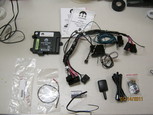
Above we have the installation instructions, remote start module (w/ 2-way DNA installed), wiring harness with a SKREEM module (RFID transmitter/antenna), antenna and cable, 2 way FOB, and a hood switch. Also is a jumper cable for the horn relay and other odds and ends (wire ties, tap screws, adhesive, etc). Overall, this doesn't look too bad. 20110113-20110114 I received the unit the day before and went through the instructions several times. Install looks a little more difficult than I originally expected, but it is still within my comfort zone. This weekend's weather doesn't look too bad, so I started prepping everything that I could in the shop so I would spend less time outside in the cold. I received the remote start module with the appropriate fuses already installed (contrary to the instructions). Then I installed the 2-way DNA (no idea what that stands for, but it handles the FOB transmit/receive) module. I have both 1-way and 2-way DNA modules, but I went ahead and installed the 2-way. 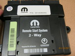
The next step was preparing the harness for the 2-way module, specifically for the hood tilt switch. The purpose of the switch is to shut off or prevent the engine from remotely starting when the hood is propped up. The switch had been updated post release from a single lead (on/off) to a two lead (high/low) switch (more on this later). The addendum for the new switch requires me to splice power (blue/red) from the other module plug to the switch plug (red). I imagine they revised the switch to prevent installers from just shorting the switch to ground. Then its just a matter of taping the harness back up. 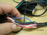
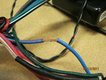
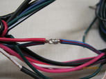
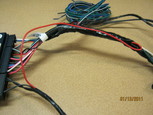
In addition to the power cable splice for the hood switch, the original hood switch cable (which is 10ft or so) can be cut and taped as it is no longer used. I opted to leave a little length of wire on the harness, just in case. Now that the harness is prepped, its ready to be installed in the car. 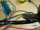
20110115 Got a fairly early start in the morning (early for Saturday anyways) and started with disconnecting the battery. Once the battery is disconnected, I start taking the dash trim off. There are a couple of screws, but most of the trim is just clipped into place. The side dash molding is removed, along with the lower dash cover. 


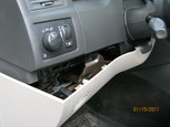
One the lower dash trim is removed, the crash plate (my words) is then removed. I couldn't help to notice that the plate had a good amount of surface rust. So I took some time to sand down the plate and put on a couple of coats of flat black Rustoleum Rust Reformer. The plate is held with four 10mm bolts. 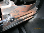
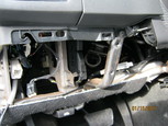
Once the plate is removed, then the ignition cover is removed. Everything is held with clips, so removing it just requires pulling the ignition switch key ring and then the cover itself. 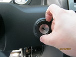
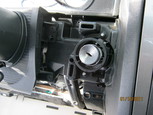
At this point, the work area is fully accessible. The next step in the directions is to mount the hood switch. This is where the instructions are vague and some prior experience is required. Needless to say, I had no prior experience. The directions state to mount the switch to the drivers side rear corner of the hood per the diagram with the wiring exiting out of the top of the switch. The quote, diagram, end quote...is a low contrast black and white photo that is about 1x1in in size. Before I get too far, keep in mind that the switch is held in place with two 1/4in self tapping screws and is required to be angled out at 45 degrees. With that being said, I had an issue finding a place to mount the switch so that it did not hit the cowl or other components. After three or four attempts, I finally found a suitable location (picture multiple holes in the inside of the hood). Fortunately, the hood is aluminum so I am not too worried about rust. Though at some point, I will use some touch-up paint so that they don't stand out. Here are some pictures of a couple of places that I attempted to install the switch. If I had just mounted closer to the hinge bolts, I would have been spot on (where the switch is mounted now). 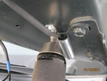
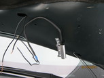
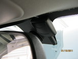
I will confess and tell you that I actually worked with the switch mounting position off and on during the rest of the install as opposed to completing this step and then moving on to the next. For now, just pretend that the hood switch is mounted in the correct location. The next step is installing the FOB antenna and running the antenna cable. This was actually pretty painless as its just pulling the A pillar cover and then running the cable along the headliner. I did have a little hiccup with the antenna regarding the adhesive. Lets just say that the antenna must have been in stock for a bit and I had issues with the antenna sticking. The fix was some double sided 3M tape (like the kind you use for their wall hooks). As seen below, I opted to mount the antenna in the blacked out portion of the windshield next to the rear-view mirror. 

Once the antenna is mounted we can now install the remote start module. The harness has a male and female plug so that the ignition switch plug is moved from the switch to the harness and then from the harness' other plug to the ignition. This will allow the module to activate the ignition. There is a single ground wire that is tied into the frame ground. 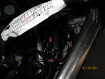
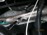
Now this is when the fun starts. There are three center splices that need to be done to finish up the install. Two of the splices are inside the cabin, one for the parking lights and the other for the brake switch. I opted to do the parking light splice first. The headlight switch pops out from the dash to access the plug. I'll splice the brown/white remote module wire to the headlight switch brown/white wire. Cut away the electrical tape to see the wire, strip about 1/2in and splice in the wire. I used a butane soldering iron to solder up the splice (not shown) and tape everything back up nice and neat. 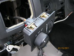
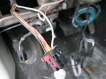
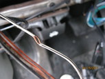
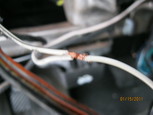
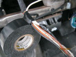
The second splice is for the brake switch. I had taken pictures of the splicing procedure and a connector, but after reading the directions yet another couple of times, I determined that I had the wrong connector (both of which have green/white wires). Fortunately this was before I had connected power back to the car. Unfortunately, I had to spend time removing the splice and then an obscene amount of time attempting to access the brake pedal switch. While messing with the switch plug, I also took breaks to relocate the hood switch to an appropriate location. And oh, by the way... the instructions state in bold print: "Caution: Do not remove the brake lamp switch from the mounting bracket. If the switch is removed from the mounting bracket, it MUST be replaced with a new switch." This is great and all, but its impossible to remove the plug from the pedal switch. With the day getting later and later, I fought with the switch plug to get the plug to release and then...pop. The whole switch comes off of the bracket (barrage of four letter words ensue). I was lucky because the retaining clip was not broken. To add insult to injury, the length of the cable for the switch is short, so a little yoga is required to splice the green/white wire. Once again, using the butane soldering iron, I solder and tape up the splice. To get the switch back into the bracket, I pressed the brake pedal down and snapped the switch back into place. I was relieved to find that it felt very secure in place and had no play. Problem is, I have no way of testing the switch until I hook the battery back up. 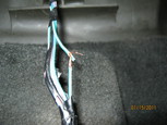
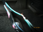
Now that the cabin splices are done, its time to wire the engine compartment up. This involves four wires. A black and black/white for the hood switch, a blue wire that is spliced into one of the coil packs (for tach), and a wire to hook the horn up to the module. To get the wires into the engine bay, I took a piece of metal clothes hanger and from the engine compartment, stick it carefully through the rubber boot sealing the cabin from the engine. 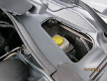
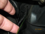

Once the hanger is through the firewall, just tape up the wires to the hanger and pull through. 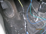
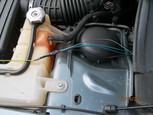
Now to wire up the dang hood switch. At this point I finally found a good mount point for the switch that doesn't scrape or bend anything. I wire it up and decide to use a multi-meter to make sure that the switch position is good to go. This is when I figure out the hard way that the switch is not a simple open/close, but a high/low. When using the continuity tester, I just listen for tone and not look at the display for resistance. So, hood up I have tone and then hood down I also have tone, what the freakin hell. I ended up removing the switch from the hood and cut the wires to the butt connectors and then test with the meter in the house. This gives me a chance to warm up a bit. After testing the switch for a couple of minutes (more like 20-30), the little light goes off in my head about the switch being high/low. Go back outside and hook switch switch back up. Now that I am fairly confident about the hood switch, its now time for the last center splice. The blue wire splices into one of the coil pack wires. This gives the module the ability to see if the engine is on and what the idle RPM is. I cannot use the engine's number six cylinder because the intake manifold is in the way. Ideally, I would have used this pack, but did not have the time or patience (another convoluted procedure) to remove the intake. So next in line is cylinder number four. Same procedure as the brake and parking light splices. Cut the tape back, strip the wire, solder, and then tape back up. I will admit I was a little hesitant about messing with the coil pack wiring. Most of the hesitation was that the installation manual states a blue/yellow wire on the pack, but I only had a solid blue (from what I could tell) and a brown/yellow wire. The coil pack only has two wires, and the remote start module wire I was splicing was blue, so I took a gamble. 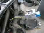
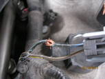
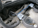
Last wire to be wired up is the green wire. This wire ties into the horn relay using a jumper wire with a crimp on the end that slips over the #85 connector of the relay and then using a butt connector to tie into the green module wire. In my rush to get done (at this point its closing in on 5:00pm), I only took a picture of the engine fuse panel with the fuse removed, sorry. 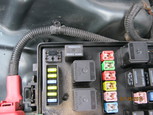
Now that the engine compartment is wired up, the next step is to install the SKREEM module antenna. The SKREEM module emulates the RFID signal that the ignition key has embedded. The antenna for the SKREEM module is a 4 wire ribbon cable that is double-sided taped around the ignition switch. Then a wire tie is used to secure the antenna. 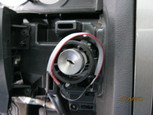
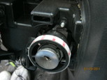
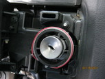
With the wiring complete and all connections made, I now program the 2-way FOB. Attached to the harness is a LED and a small push button switch. I won't go into the programming procedure since its pretty complicated using the programming button on the FOB, button on the module, and brake pedal. I went ahead and did the procedure for programming the FOB. This was probably not needed, as the FOB shipped with the DNA module. After that, the module needs to know what the idle speed of the engine is. This involves starting the engine, car will chirp every three seconds until the idle speed is set using the brake pedal. Once the idle speed is set, then its time to program the SKREEM module. The procedure is the same as programming another spare key. You need two existing ignition keys (not the door keys) to program the unit. Again, I will not go into the procedure as its complicated and fully documented in the installation manual. After it was all said and done, I go ahead and remove the ignition key and then press the start button on the remote-start FOB. Within seconds, the car starts up and works beautifully. There is a checklist of tests to perform and all pass successfully. With the unit working as it should, its time to secure the remote-start module using wire-ties and then putting all of the trim back on. Here is a before and after picture of the crash plate. Its out of view, so I just left it with the flat-black. 
20110115 - Post install notes The install was neither as easy or as hard as I thought it would be. Funny thing is that the "easy" parts were hard and the hard parts were easy. Total time spent on install was around five hours (had an errand with the wife and kid to run during the install). A couple of things that really busted my rear: 1. Removing the lower dash panel completely (by disconnecting the parking brake release) is a royal pain in the arse. I fought with that dang thing for more than an hour at different times during the install. I had tried to work around it, but in the end, had to remove the release in order to obtain the yoga position to splice the green/white brake light wire. Its one of those one way arrowhead push clips. I ended up breaking part of the clip on accident removing the release handle. At least it went back in securely. 2. The dang hood switch. The hood doesn't just drop down, it drops down and slides back. This makes it hard to determine where the switch is going to scrape, cut, or otherwise damage itself and/or the cowl (that I had just painted over the fall). It also doesn't help that along with the limited clearance space, the switch sticks out a good 2in from the hood. Unless you have installed one before, expect to have a couple of sets of holes in your hood. I would at least suggest using the double sided tape to test locations out before you drill. At least it's inside the engine bay, so not the end of the world. 3. Brake light switch from hell. I realize that its a pretty significant component, but dang. I never did figure out how to remove the plug from the switch and I can't imagine the position it would take to splice that wire in-place. In addition, there is very little cable slack (by design) to work with. Between this and the parking brake release handle, my legs are still sore from the yoga position (the road kill squirrel position?) I had to use just to get to that darn thing. 4. I highly suggest gloves. The shear amount of exposed tap screws behind the dash will make swiss cheese of your hands. Blood and hot solder do not mix, nor feel good. Thats pretty much it. The install probably would have went better if it was about 30 degrees warmer, but overall, I can't complain too much. It was nice being able to start my car this morning before work from inside the house when the outside temperature is 15 degrees. Now to remember to turn the heating controls to the right settings when I park the car. Back to Chrysler Projects |
|


